Final Assembly
Go back to the Starting Assembly tab, ready to insert your custom parts back into the assembly
Part Studio vs Assembly
Before starting the assembly, let's clarify the difference between these two concepts:
- Part Studio -- Where you model parts. You can create multiple parts in a single Part Studio.
- Assembly -- Where you define the mechanical relationships between parts, such as which parts are fixed together and which can rotate.
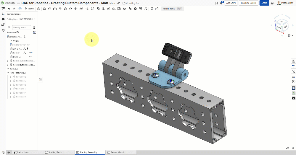
We built the Base and Sensor Mount in the Part Studio during Chapters 7 and 8. Now we need to put them back into the Assembly and define their connections.
Insert Parts into the Assembly
- In the Part Studio, click the "Insert and go to Assembly" yellow button
- Select both the Base and Sensor Mount parts
- Click the green checkmark ✓ to confirm
You'll be automatically taken back to the assembly, where the two new parts are now present.
You should see the Base and Sensor Mount parts in the assembly, along with the tube and sensor from before.
Mate Connectors
Mate Connectors are small coordinate systems that Onshape automatically creates at circle centers, hole centers, edge midpoints, and other key locations on parts. When you create a mate, you're aligning two mate connectors together.
Add Mates
Clean Up Temporary Mates
- In the left panel, find Fastened 2 (it was temporarily fixing the sensor)
- Delete this mate
- The sensor will detach from its position -- this is expected
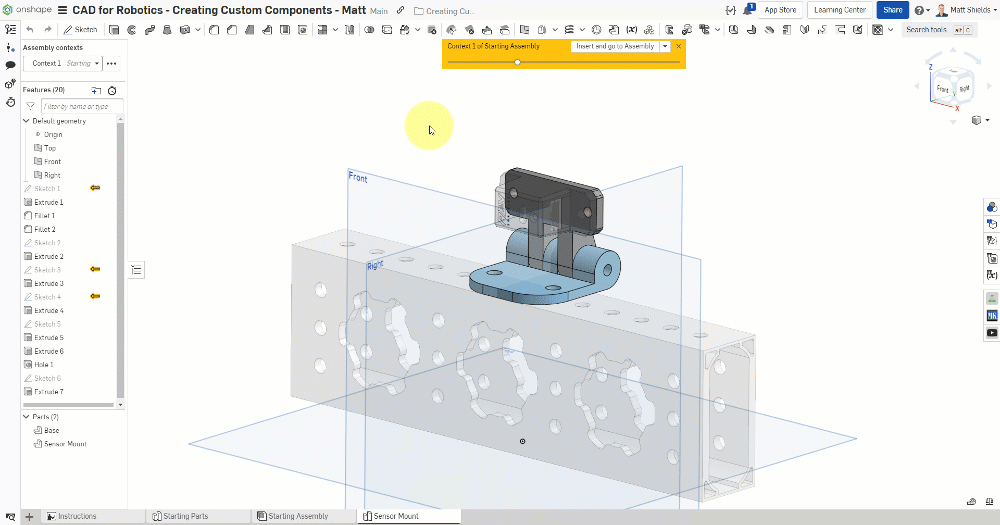
Drag Parts Apart
Drag the parts slightly apart to make it easier to select mate connectors in the next steps.
Fix Base to Tube
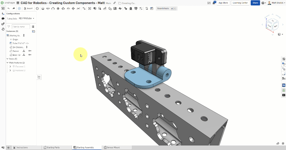
- Create a Fastened mate
- First connector: the hole center on the tube
- Second connector: the corresponding hole center on the Base
- Confirm the Base sits flush on top of the tube
Connect Sensor to Sensor Mount
- Create a Fastened mate
- First connector: the sensor's mounting hole center
- Second connector: the Sensor Mount's corresponding hole center
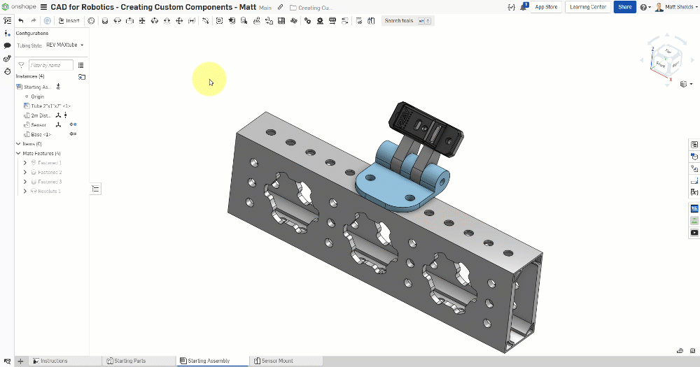
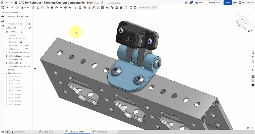
Change to Revolute Mate
- Change the mate between the sensor and Sensor Mount to a Revolute mate
- First connector: the Sensor Mount's outer cylindrical face
- Second connector: the Base's inner cylindrical face
- After confirming, try dragging the sensor mount -- it should rotate around the axis!
Dragging the Sensor Mount should show it rotating around the support post, carrying the sensor along with it.
⚠️ Common Issues
- Revolute mate won't rotate? — Check that you selected the correct concentric cylindrical faces (Sensor Mount outer and Base inner), not flat faces or edges.
- Parts flew away? — Press F to zoom to fit, or undo (Ctrl+Z) and try again.
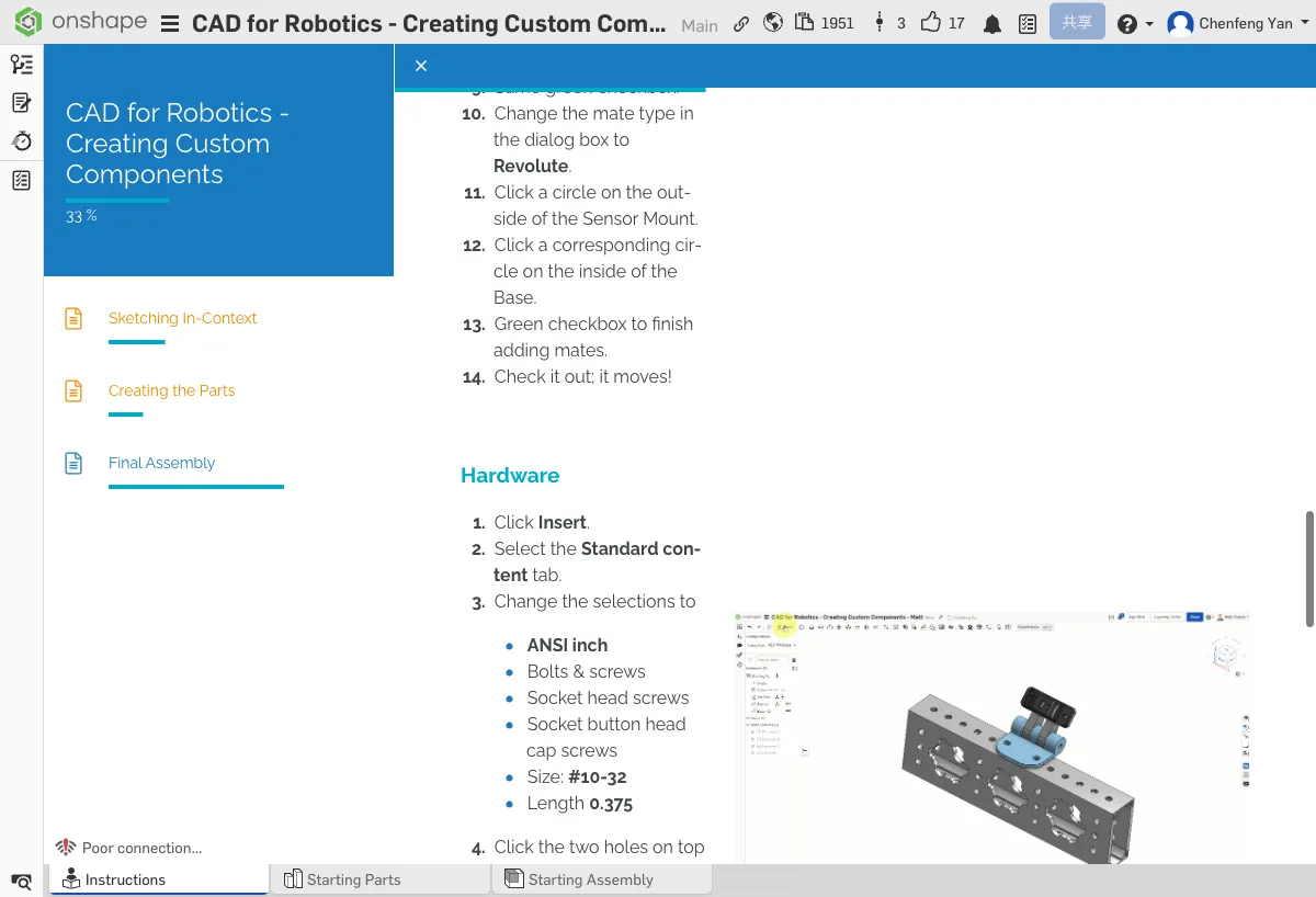
Add Standard Hardware (Bolts and Nuts)
Insert Bolts
- Click Insert → Standard content (standard parts library)
- Expand ANSI inch → Bolts and screws
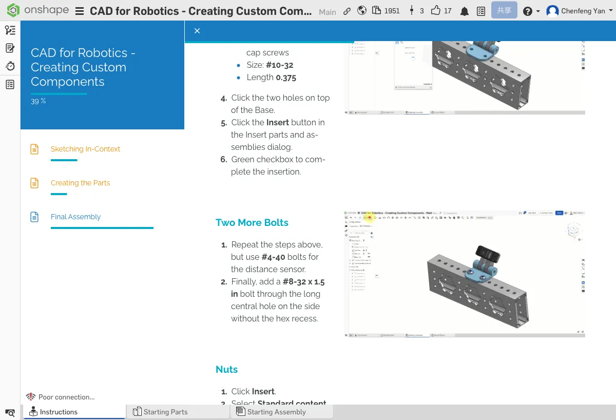
- Select Socket button head cap screws
- Choose #10-32 x 0.375"
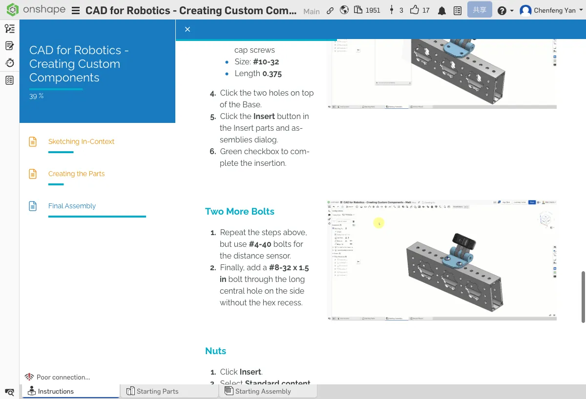
- Click the two mounting holes on the Base to place the bolts
- Insert #4-40 bolts into the sensor mounting holes
- Insert #8-32 x 1.5" bolts into the long holes in the center support posts
Insert Nuts
- Click Insert → Standard content → Nuts
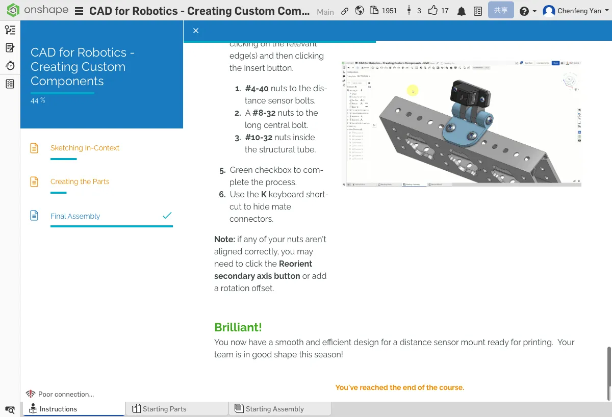
- Insert #4-40 nuts at the bottom of the sensor bolts
- Insert #8-32 nuts at the bottom of the center bolts
- Insert #10-32 nuts at the bottom of the tube-side bolts
Press K to toggle mate connector visibility for a cleaner view.
Congratulations! You've designed a complete adjustable-angle distance sensor mount. The assembly should contain: the tube, sensor, Base, Sensor Mount, and all bolts and nuts.
⚠️ Common Issues
- Can't find standard parts? — Make sure you selected Standard content in the Insert panel, not Current document or Other documents.
- Bolt facing the wrong way? — Use Flip primary axis in the Mate dialog to flip it.
- Nuts don't line up? — Make sure the nut spec matches the bolt spec (#4-40 with #4-40, #8-32 with #8-32, #10-32 with #10-32).
Summary
You now have a distance sensor mount design that can be 3D printed or CNC machined. It mounts on a tube and allows the sensor angle to be adjusted.
Discussion Questions
- What is a mate connector? What role does it play in assemblies?
- What's the difference between a Fastened mate and a Revolute mate? When should you use each?
- Why design parts in In-Context mode instead of in a blank Part Studio?
Extra Practice Suggestions
- Try designing other custom parts in the drivetrain assembly (e.g., sensor brackets, battery mounts)
- Take the Managed In-Context Design course on Onshape Learning Center for advanced in-context modeling best practices
- Try modifying the Sensor Mount dimensions to fit different-sized sensors
Quick Quiz
What's the difference between a Fastened mate and a Revolute mate?
What You Learned in This Chapter
- Part Studio is for modeling; Assembly is for defining connections
- Fastened mates lock parts together; Revolute mates allow rotation
- Standard content provides off-the-shelf bolts and nuts