Creating Parts
Continue working in your Sensor Mount Part Studio
A. Extrude the Sketch
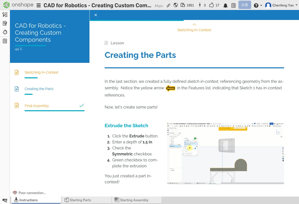
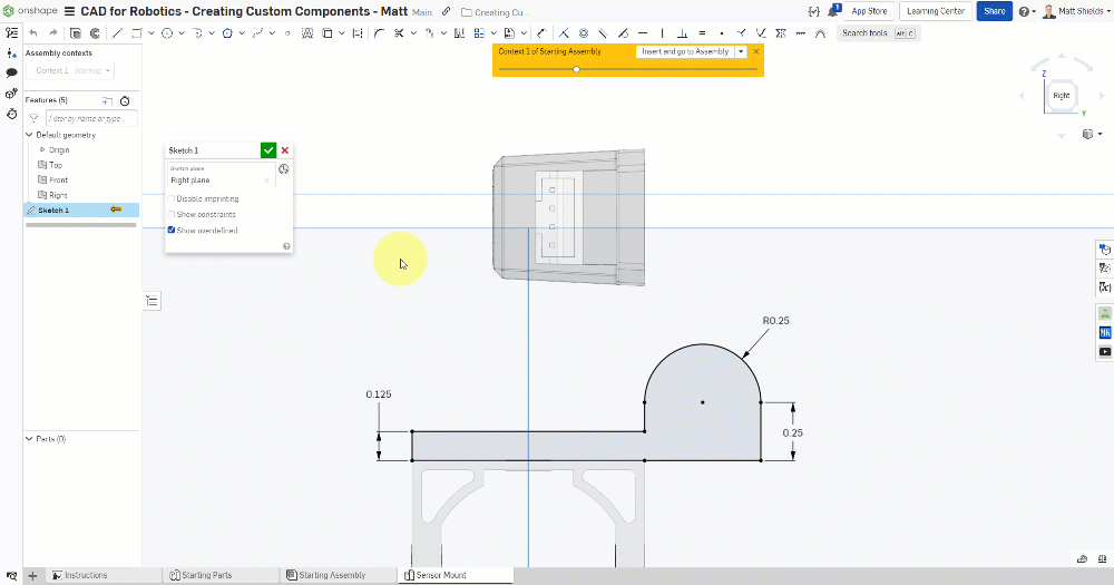
- Select the Extrude tool
- Select the sketch you completed in the previous chapter
- Set the depth to 1.5 in
- Check Symmetric (extrudes equally on both sides, 0.75 in each)
- Click the green checkmark ✓ to confirm
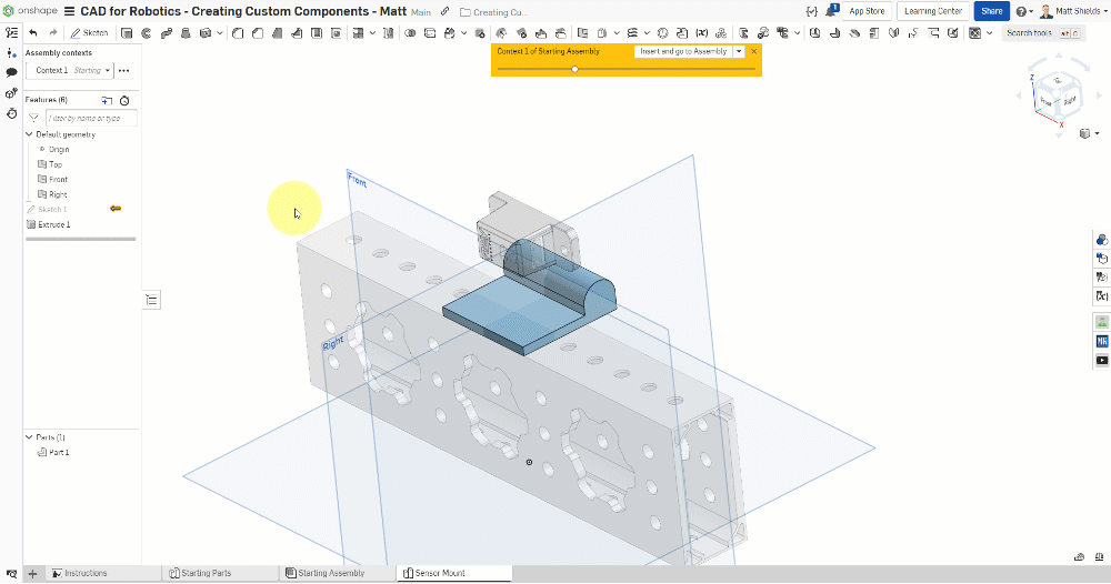
Congratulations! You just created your first solid part in context!
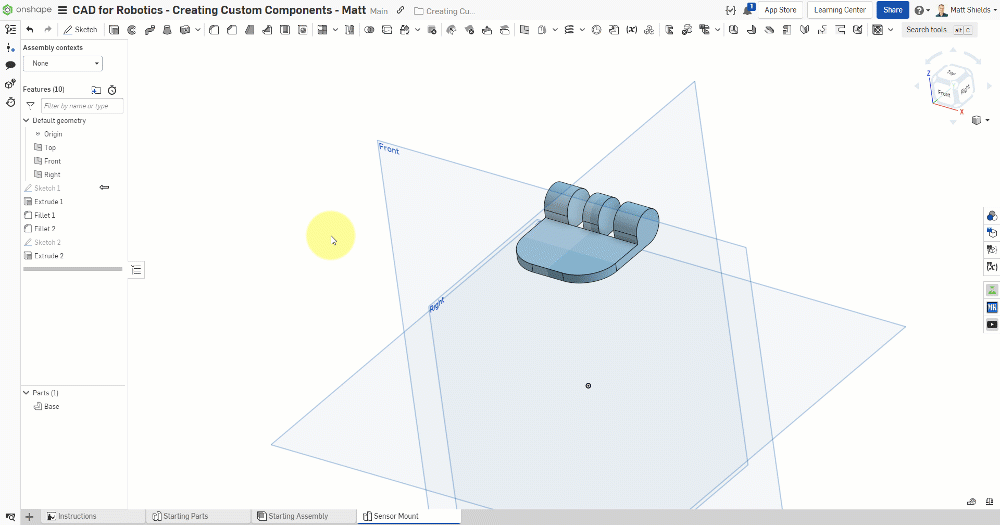
An L-shaped cross-section solid should appear above the tube, with the transparent assembly still visible in the background.
B. Add Fillets and Cutouts
Turn Off Assembly Context
The following operations don't need the assembly for reference. Set Assembly context to None in the left panel for a cleaner view.
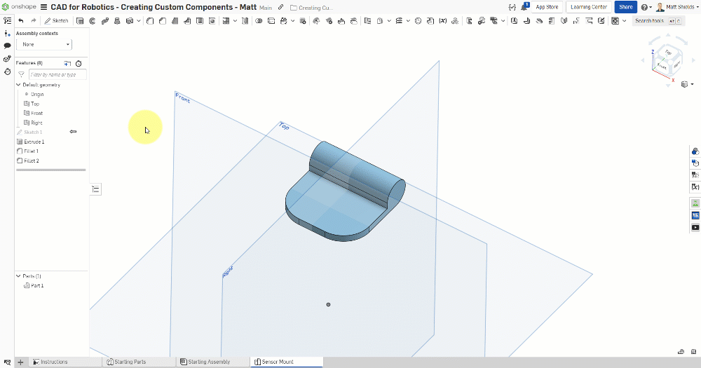
Add Fillets
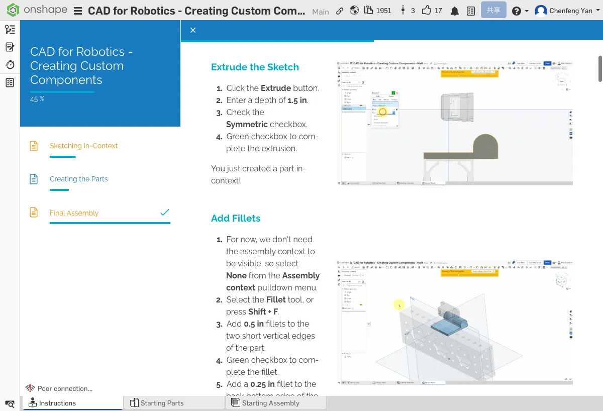
- Select the Fillet tool (shortcut Shift+F)
- Select the two short vertical edges of the part and set the fillet radius to 0.5 in
- Then select the bottom rear edge and set the fillet radius to 0.25 in
- Click the green checkmark to confirm
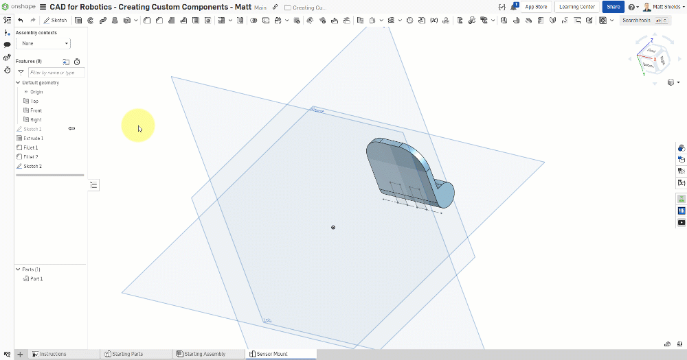
Create a Cutout Sketch
- Create a new Sketch on the bottom face of the part
- Switch to the Bottom view
- Use the Use tool (U key) to select the bottom edge, then press Q to convert it to Construction (reference line)
- Use Corner rectangle (shortcut G) to draw a 0.25 x 0.5 in rectangle
- Dimension the rectangle to be 0.375 in from the left edge
- Use the Mirror tool with the Right plane as the mirror axis to mirror the rectangle to the other side
- Commit the sketch
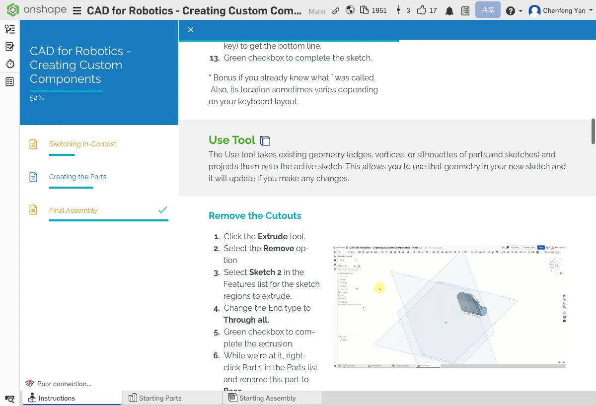
Cut the Slots
- Select the Extrude tool
- Select the rectangle sketch you just created
- Set the type to Remove (subtract material)
- Set End type to Through all (cut through the entire part)
- Click the green checkmark to confirm
In the feature tree on the left, right-click and rename this part to Base.
The Base part should have rounded edges and two symmetrical cutout slots.
⚠️ Common Issues
- Extrude Remove has no effect? — Make sure you selected Sketch 2 (the cutout sketch) and that End type is set to Through all.
- Mirror not working? — Make sure you selected the Right plane as the mirror axis and that the rectangle is drawn on one side, not centered.
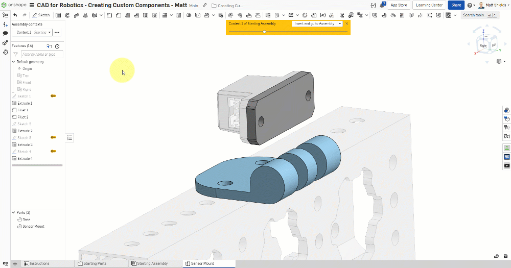
C. Mounting Holes and Sensor Mount
Reference Tube Holes
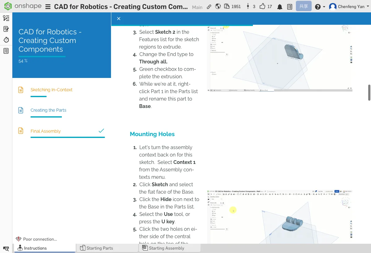
- Switch Assembly context back to Context 1
- Create a new Sketch on the top face of the Base part
- Hide the Base part so you can see the tube below
- Use the Use tool to select two holes on the tube
- Unhide the Base part
- Use Extrude Remove → Through all to cut these two holes through the Base
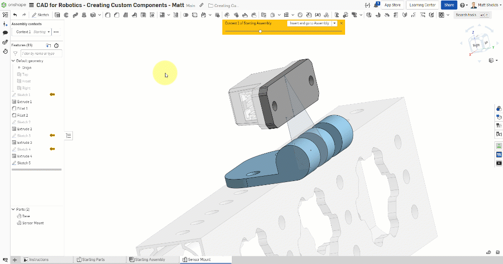
Create the Sensor Mount
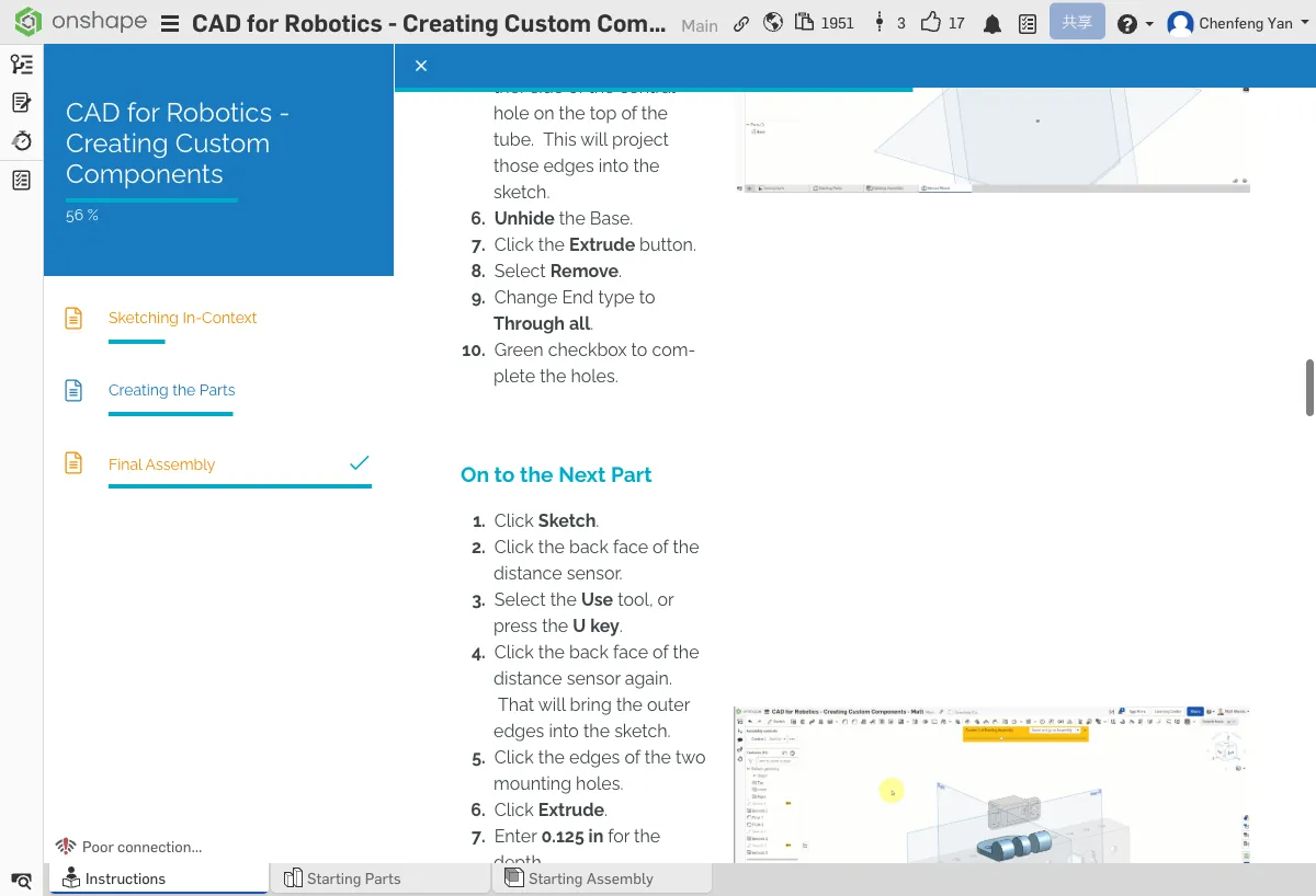
- Create a new Sketch on the back face of the sensor area on the Base
- Use the Use tool to select the sensor's outer edge and mounting holes
- Commit the sketch
- Use Extrude to extrude 0.125 in
- Rename the new part to Sensor Mount in the feature tree
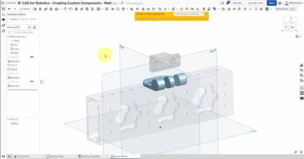
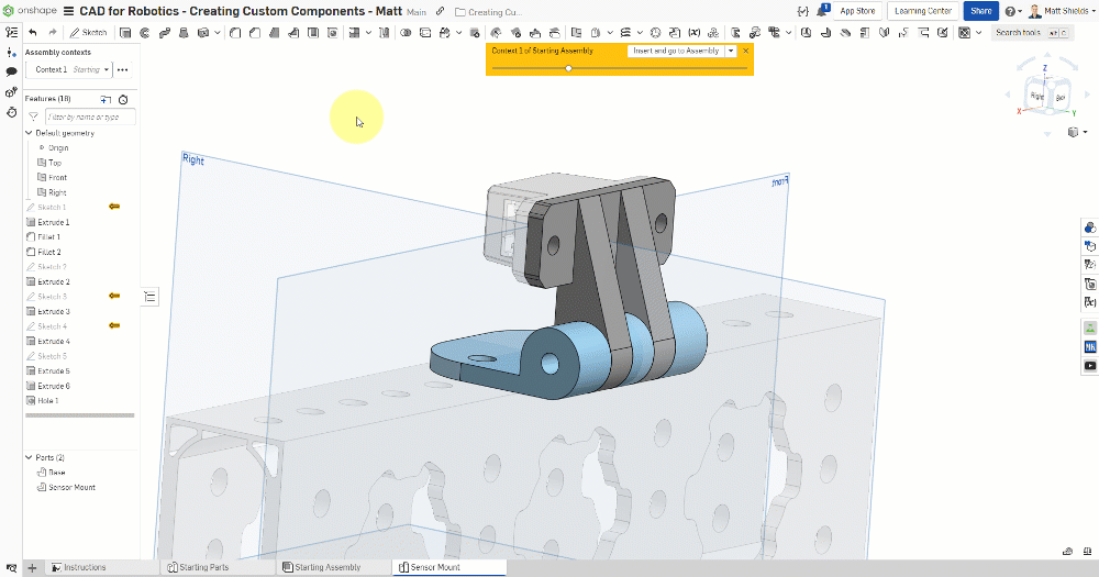
The feature tree should contain two separate parts: Base and Sensor Mount.
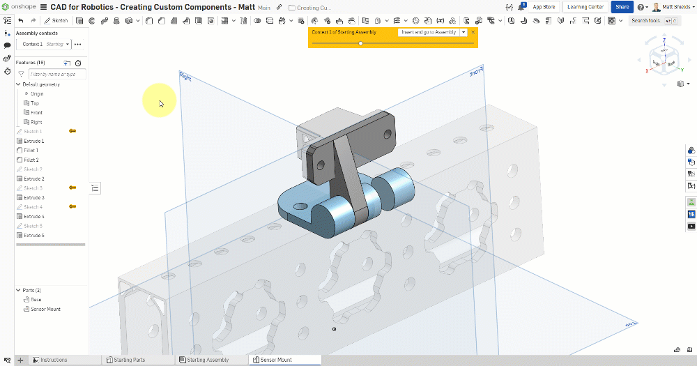
D. Support Structure and Details
Add Support Structure
- Create a new Sketch on a side face of the Base
- Use Center point circle (shortcut C) to draw a circle
- Use the Use tool to reference the right edge
- Draw tangent connecting lines
- Use Extrude Add, set Merge scope to Sensor Mount, and End type to Up to face
Second Support
- Extrude again with End type set to Up to face
- Also set Second end position (bidirectional extrude to face)
Drill Holes
- Select the Hole tool
- Set the type to Simple
- Set the spec to ANSI #8
- Select a mate connector to position the hole
- The hole should pass through both parts
Nut Recess
- Create a new Sketch and select Inscribed polygon
- Set to 6 sides (hexagon, to fit a nut)
- Width: 0.345 in
- Use Extrude Remove with a depth of 0.1875 in
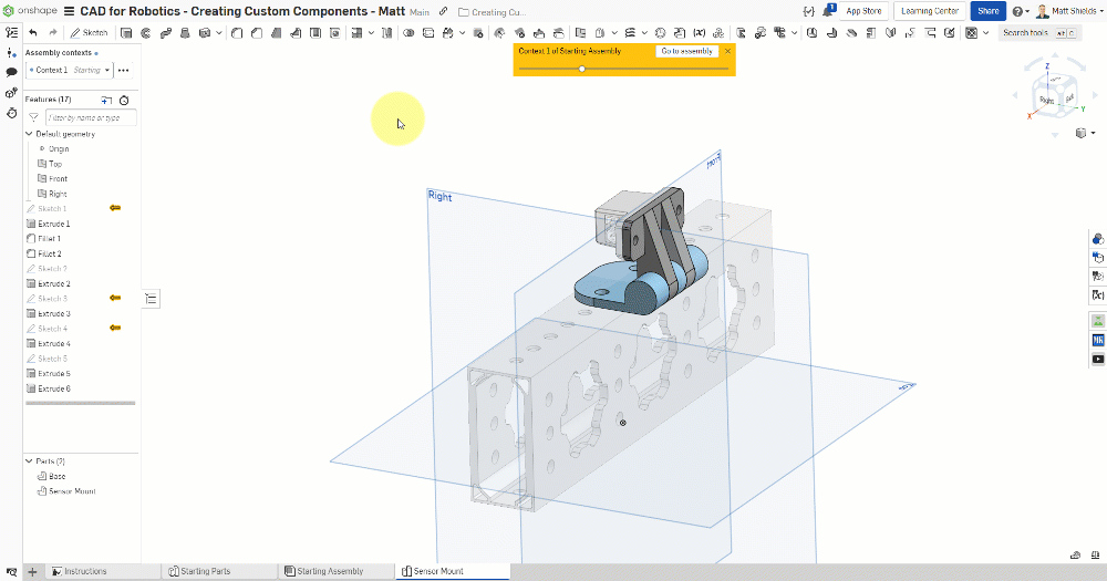
The Base should have cutout slots, mounting holes, and support structures. The Sensor Mount should have sensor mounting holes and a nut recess. Both parts are connected by the support posts.
⚠️ Common Issues
- Can't select a face for Extrude Up to face? — Make sure Assembly context is set back to Context 1 so you can see the faces in the assembly.
- Hole tool not working? — Make sure you selected the correct mate connector as the hole's positioning point.
- Inscribed polygon isn't hexagonal? — Confirm the number of sides is set to 6.
Keyboard Shortcuts Review
| Shortcut | Function |
|---|---|
| F | Zoom to fit |
| Shift+F | Fillet |
| U | Use tool |
| Q | Toggle Construction mode |
| L | Line |
| C | Circle |
| G | Corner rectangle |
| N | Normal to (front view) |
| D | Dimension |
| T | Tangent constraint |
| V | Vertical constraint |
Quick Quiz
What does the Fillet tool do? (One word)
What You Learned in This Chapter
- Extrude turns a sketch into a solid body
- Fillets round edges for safety and aesthetics
- The Hole tool drills standard-spec holes