CNC Milling
A. What is a CNC Router/Mill?
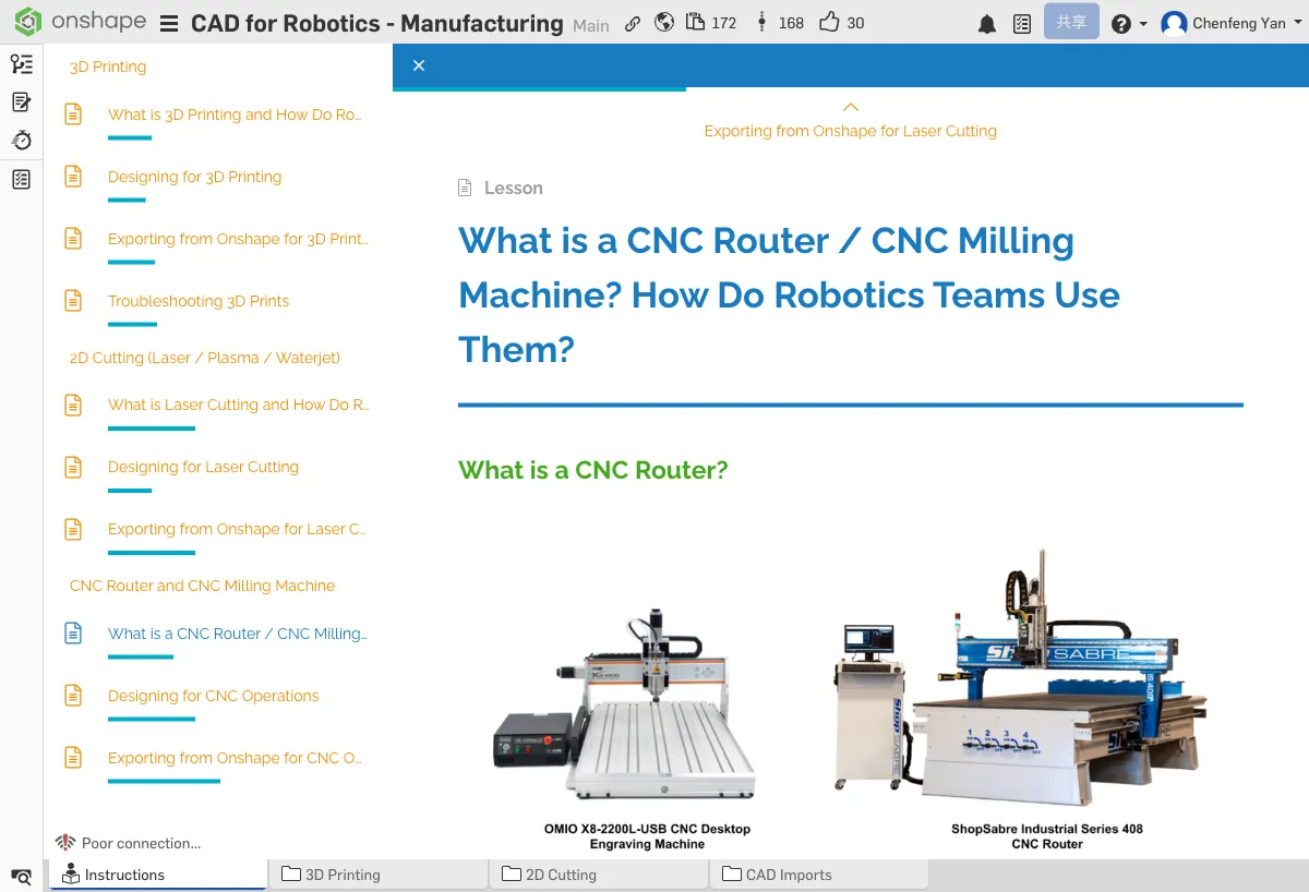
CNC Router
A CNC router uses a high-speed rotating cutting tool to cut and mill sheet materials, similar to a large automated engraving machine. It's typically used to machine softer materials like wood, plastic, and aluminum.
CNC Mill
A CNC mill is more precise and rigid than a router, capable of machining harder metals (such as steel and titanium). Mills can perform more complex 3D machining operations.
Why Do Robotics Teams Use CNC?
- Precision metal plates — Machining accuracy down to 0.05mm
- Custom mounting plates — Precise hole positions and contours
- Gearbox housings — Structural parts requiring precise fits
Common Machining Operations
- Aluminum plate cutting — Cutting aluminum sheets along a contour
- Hole drilling — Precise hole placement
- Pocket milling — Milling recesses and pockets into sheet material (to reduce weight)
B. CNC Design Tips
Workholding
Parts must be securely clamped before machining. Design considerations include:
- Leave clearance for clamps — the area occupied by fixtures cannot be machined
- Consider using bolt holes for fixturing (drill fixture holes first, then machine the contour)
- Avoid designing shapes that cannot be clamped
Machine Work Envelope
Every CNC machine has a work envelope — the maximum part size it can handle. Before designing, find out the work envelope of the CNC machine available to you. A typical small CNC router has a work envelope of about 300mm x 200mm.
Sharp Corners vs. Fillets
If you use a 6mm diameter tool, all internal corners will have at least a 3mm radius. You must account for this in your design, or parts won't assemble correctly.
Available Tools
Different tool diameters determine the minimum feature size you can machine:
- Large tools (6mm+) — Faster machining, but larger minimum feature size
- Small tools (1-3mm) — Can machine fine features, but slower and more prone to breaking
- Design with features that can be completed by larger tools first; only use small tools when necessary
If you use a 4mm diameter tool, what is the minimum internal corner radius? If a square hole requires perfectly sharp corners, can CNC achieve that? What alternatives are there?
C. Exporting from Onshape for CNC
Face DXF
Suitable for 2D profile machining (cutting aluminum plates, etc.):
- Right-click the machining face of the part
- Select Export as DXF
- The DXF file contains all contours and hole positions for that face
Sketch DXF
If you need to export specific toolpaths (rather than the part face contour), you can export a sketch directly as DXF:
- Right-click the sketch tab
- Select Export as DXF
STEP Files
Suitable for CAM software that needs a 3D model (for pocket milling and other 3D operations):
- Right-click the part
- Select Export
- Choose STEP as the format
Common CAM Software
CAM (Computer-Aided Manufacturing) software generates the toolpaths for CNC machining:
- Fusion 360 CAM — Full-featured, free for students
- Mastercam — Industry-grade CAM software
- Onshape Built-in CAM — Some CAM features are available directly within Onshape
- DXF — 2D profile machining (cutting, drilling)
- STEP — 3D machining (pocket milling, surface machining) or when you need the full 3D model in CAM
If you're cutting an aluminum plate, which format should you export? What about milling a part with pockets?
Quick Quiz
Why can't CNC create perfect 90° inside corners? (Hint: think about the tool shape)
What You Learned in This Chapter
- CNC mills machine precision metal parts
- Internal corners must have fillets (equal to tool radius)
- Use DXF for 2D, STEP for 3D exports