Assembling the Full Drivetrain
Open your copied document in Onshape and switch to the Complete Drivetrain tab
A. Inserting Parts
Step 1: Switch to the Complete Drivetrain Tab
Find the Complete Drivetrain tab at the bottom of the document and click to switch to it. This tab is where you'll assemble the final complete drivetrain.
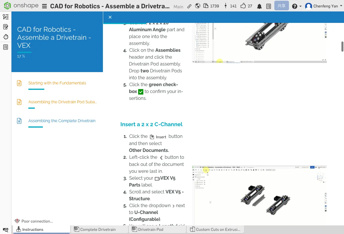
Step 2: Insert Structural Parts and Pods
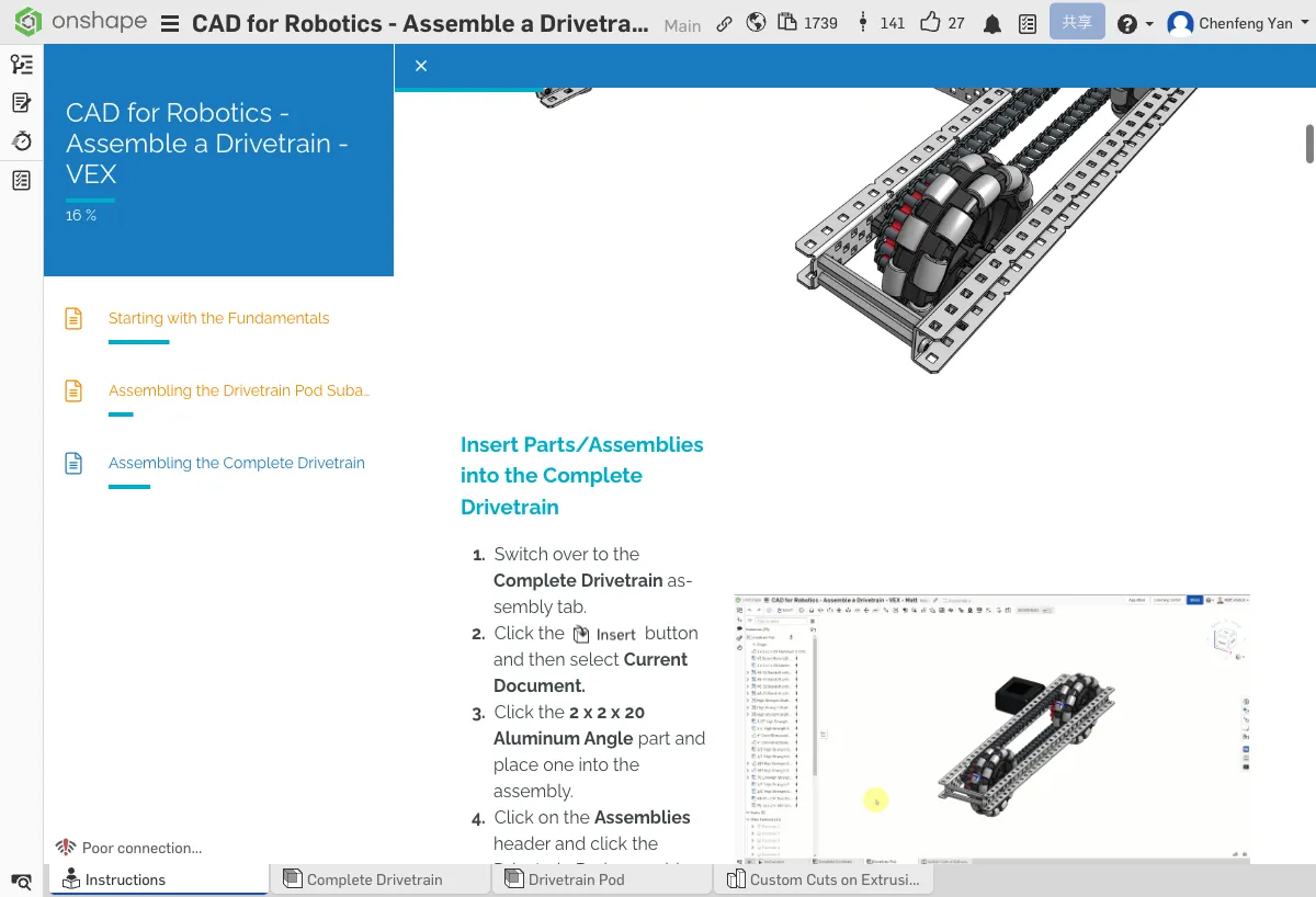
- Click Insert → Current Document
- Insert 2x2x20 Aluminum Angle x 1
- Insert Drivetrain Pod (the sub-assembly you completed in Chapter 5) x 2
Step 3: Insert U-Channel
- Click Insert → Other documents → VEX V5 Parts
- Open VEX V5 - Structure
- Select U-Channel Configurable
- Configure it to 10 inches
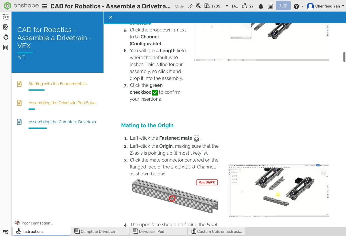
Step 4: Fix U-Channel to Origin
- Create a Fastened mate
- Fix the U-Channel to the assembly's Origin
You should see: 1 U-Channel (fixed to origin), 2 Drivetrain Pods, and 1 Aluminum Angle.
⚠️ Common Issues
- Can't find Drivetrain Pod? — Make sure you completed the Pod assembly in Chapter 5. It should appear in the Current Document list.
- U-Channel length is wrong? — After inserting, check the Configuration in the left panel and confirm it's set to 10 inches.
B. Connecting the Two Pods
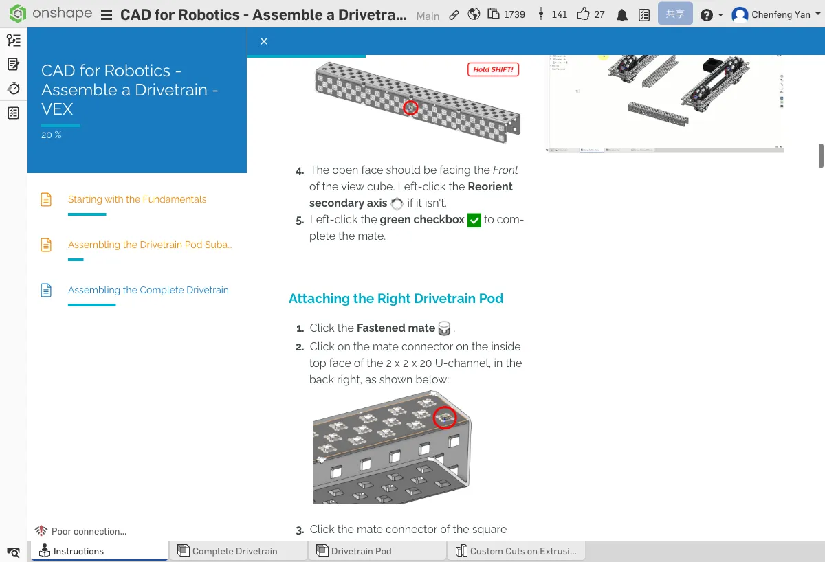
Step 5: Attach the Right Pod
- Create a Fastened mate
- Connect the right Drivetrain Pod to the rear-right of the U-Channel
- Make sure the Pod's wheels face outward
Step 6: Attach the Left Pod
- The left Pod needs to be rotated 180° first (for mirror placement)
- When creating the Fastened mate, use Flip primary axis or manually rotate
- Connect the left Pod to the left side of the U-Channel
- Confirm both Pods are symmetrical
Step 7: Attach the Front Angle
- Create a Fastened mate
- Fix the 2x2x20 Aluminum Angle to the front of the drivetrain
- The Angle spans both Pods, adding structural rigidity
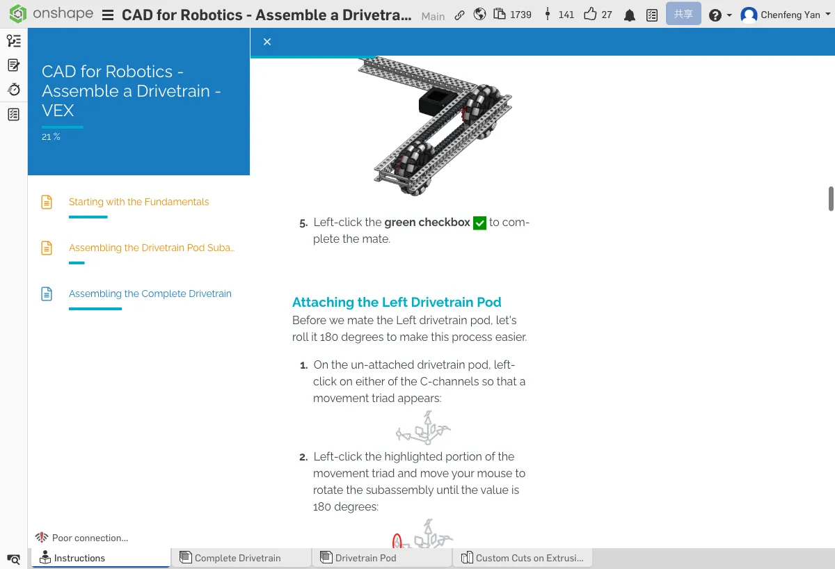
Viewed from the top, the drivetrain should be left-right symmetrical. The wheels on both Pods face outward (left and right), and the Angle connects them at the front.
⚠️ Common Issues
- Left Pod facing the wrong way? — Use Flip primary axis in the Mate dialog to rotate 180°, or delete the mate and recreate it.
- Pods aren't symmetrical? — Use the View cube to switch to Top view and verify both Pods are mirror images of each other.
C. Adding Bolts and Nuts
Step 8: Insert Custom Spacers
- Insert 0.875-inch custom spacers from the current document or parts library
- You'll need 6 total
- Use Fastened mates to fix the spacers at the connection points between the two Pods
Step 9: Insert Screws

- Insert 1-1/4 inch screws and 1-1/2 inch screws
- Use Fastened mates to fix the screws on top of the spacers
- You can fix one first, then copy and paste to the remaining positions

Step 10: Install Nylock Nuts
- Click Insert → VEX V5 Parts Library
- Find #8-32 Nylock Nut
- Insert 6 of them
- Use Fastened mates to fix each nut to the bottom of its corresponding screw
Congratulations! Your complete drivetrain should include two Pods, a U-Channel, an Angle, spacers, screws, and nuts. Compare it with the reference model to make sure nothing is missing.
⚠️ Common Issues
- Screw length not right? — Make sure you're using the correct screw length (1-1/4" or 1-1/2"). Different positions require different lengths.
- Nuts in the wrong position? — Nylock nuts should be fixed at the bottom of the screws after they pass through the parts, serving as locking fasteners.
Summary
The drivetrain is just the starting point for your robot. From here, you can continue adding:
- Control System — VEX V5 Brain, battery, controller receiver
- More Motors — To drive additional mechanisms (intake, launcher, etc.)
- Reinforcement — Extra structural supports to make the drivetrain more rigid
- Scoring Mechanisms — Design intake, launcher, and other mechanisms based on game requirements
Keep exploring Onshape and turn your ideas into reality!
What You Learned in This Chapter
- Sub-assemblies can be reused multiple times
- Rotating 180° before mating creates a symmetric installation
- Copy and paste speeds up placing repeated parts
Quick Quiz
What main structural part connects the two Pods?