CNC Basics & 3D Printing
Copy the Document
As before, start by copying the tutorial document to your own Onshape account.
Click to open the Onshape tutorial document in a new tab, then copy it to your account
A. The Magic of CNC
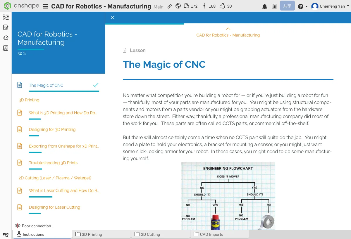
What is CNC?
CNC = Computer Numerical Control. In simple terms, it uses a computer to control a machine that automatically manufactures parts. You design the part in Onshape, then let the machine produce it precisely according to your design.
Common CNC Tools
- 3D Printer — Builds parts layer by layer with material (this chapter's focus)
- Laser Cutter — Cuts flat materials with a laser beam (Chapter 14)
- CNC Mill / Router — Removes material with a rotating cutting tool (Chapter 15)
These tools allow robotics teams to manufacture precise custom parts — shapes you can't buy off the shelf, special mounting brackets, or structural components that perfectly match your design.
B. What is 3D Printing?
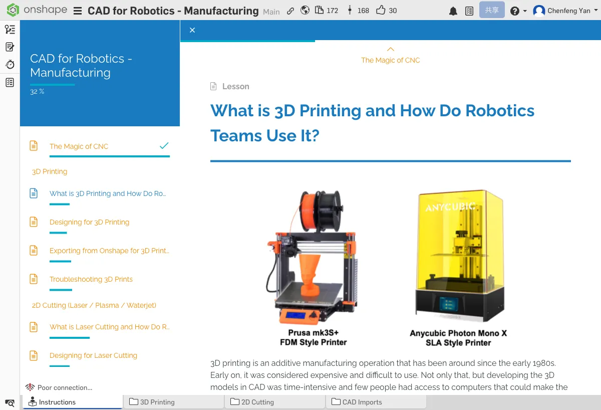
How 3D Printing Works
3D printing (also called additive manufacturing) creates parts by depositing material layer by layer (usually plastic filament like PLA or PETG). The printer's nozzle heats the filament to melt it, then lays it down one layer at a time following the designed path.
Why Do Robotics Teams Use 3D Printing?
- Rapid prototyping — Turn a design into a physical part within hours; test ideas quickly
- Custom parts — Manufacture specialized parts you can't buy commercially
- Complex shapes — Create shapes that are difficult or impossible with traditional machining
Common Uses
- Motor mounts and sensor brackets
- Gearbox housings
- Gripper components
- Cable management clips
Prototyping Examples
Many top robotics teams use 3D printing for rapid prototyping:
- Spectrum #3847's Prototyping Blocks — Standardized 3D-printed building blocks for quick prototyping
- HYPE #5254's HYPE Blocks — A similar modular prototyping system
- Quick Build Clamping Blocks — Printed blocks for quick clamping and fixturing
- Protopipe — A prototyping method using 3D-printed connectors with tubing
Think about which parts on your robot could be 3D printed. List at least 2 possible use cases.
C. Designing for 3D Printing
The Printing Workflow
The complete workflow from CAD model to physical part:
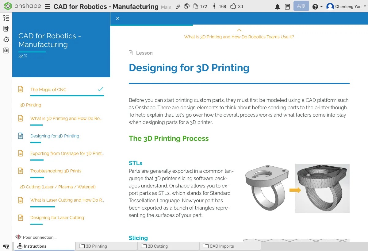
- CAD Model — Design the part in Onshape
- Export STL — Convert the model to 3D printing format
- Slicer Software — Use Cura/PrusaSlicer to "slice" the model into layers
- G-code — The slicer generates instructions that control printer movement
- Print — The printer follows the G-code to print layer by layer
Designing for Strength
3D-printed parts have an important characteristic: print orientation affects part strength. The bond between layers is the weakest link.
Key Features
- Overhang angle — Overhangs less than 45 degrees from vertical don't need support structures
- Holes — Holes printed vertically come out rounder and more accurate
- Wall thickness — At least 2mm; walls that are too thin will break easily
Embedded Nuts and Heatset Inserts
3D-printed parts often need to connect to other parts. Tapping threads directly into plastic strips easily, so a better approach is using embedded nuts or heatset inserts.
Supports and Infill
- Less support is better — Support structures increase print time and material use; they also leave rough surfaces after removal
- Infill percentage — 20-50% is usually sufficient. 100% infill wastes time and material, and makes the part heavier
D. Exporting STL from Onshape
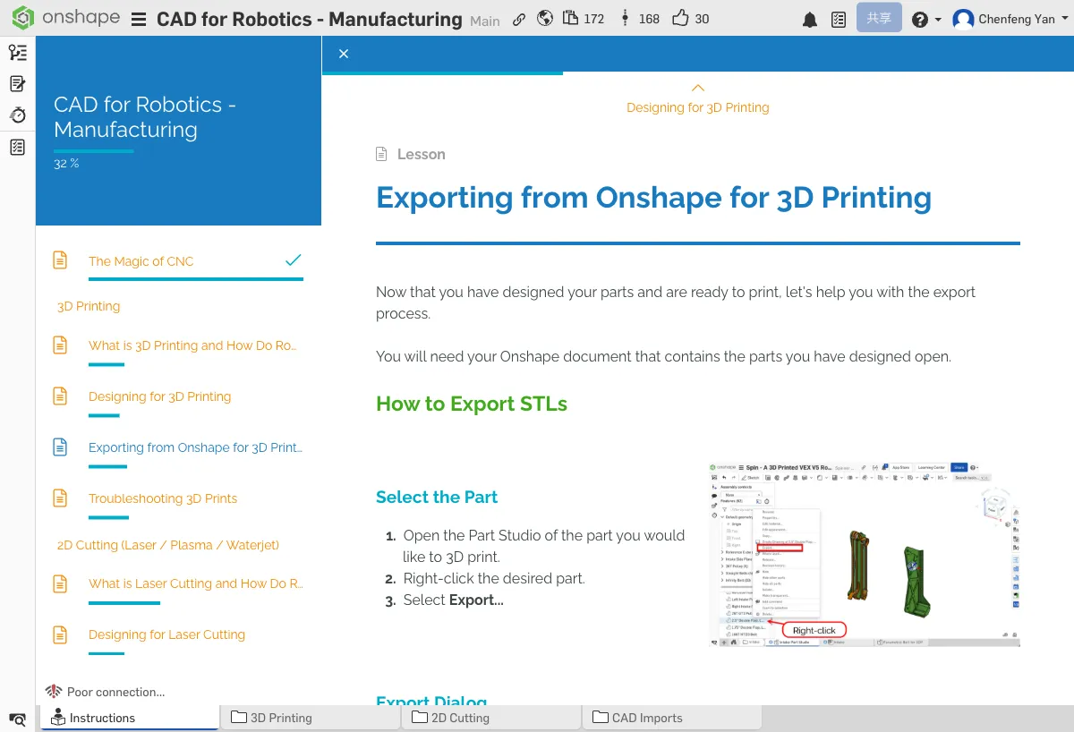
Export Steps
- Right-click the part you want to export in the parts list
- Select Export
- Choose STL as the format
- Settings: Select Binary STL (smaller file size) and Fine resolution (more detail)
- Click export and save the file
Exporting Multiple Parts
If you need to print multiple parts, you can export them one by one or select multiple parts to export together. We recommend exporting individually so you can adjust print parameters separately in the slicer.
Importing into Slicer Software
The exported STL file needs to be imported into slicer software (like Cura or PrusaSlicer) to generate print instructions. Common slicer settings:
- Layer height — 0.2mm for general use / 0.12mm for fine detail (thinner layers = finer quality but longer print time)
- Infill — Choose 20-50% based on the part's purpose
- Supports — Enable when there are overhanging sections
- Speed — Slower = better quality, but longer print time
E. 3D Printing Troubleshooting
Elephant's Foot
The bottom of the print bulges outward, looking like an elephant's foot. This happens when the first layer temperature is too high or the print bed is too close to the nozzle.
- Lower the first layer temperature
- Increase the Z-offset (move the nozzle slightly farther from the bed)
Stringing
Fine strings appear between parts. This is caused by material oozing from the nozzle during travel moves.
- Enable retraction
- Lower the print temperature slightly
Poor Bed Adhesion
Parts detach from the build plate during printing.
- Level the print bed
- Use a glue stick or PEI print surface for better adhesion
Warping / Melting
Parts warp or fine details melt.
- Lower the print temperature
- Increase cooling fan speed
What should you do when you encounter stringing? What about elephant's foot? Make sure you understand the solutions for these common issues.
Open the tutorial document, select a part, and follow the steps to export an STL. If you have slicer software, try importing it to see the result.
Quick Quiz
What file format do you export from Onshape for 3D printing?
What You Learned in This Chapter
- CNC uses computers to control machines for automated manufacturing
- 3D printing is great for complex shapes and rapid prototyping
- Print orientation affects part strength