Laser / Plasma / Waterjet Cutting
A. What is Laser Cutting?
How Laser Cutting Works
A laser cutter uses a high-energy laser beam to cut materials. Common materials include acrylic, wood, and thin metal. Laser cutting offers very high precision with smooth, clean edges.
Kerf
Kerf is the width of material removed by the laser, typically between 0.1-0.3mm. You need to account for kerf in your designs:
If you design a tab exactly 10mm wide to fit into a 10mm slot, after cutting, the tab will be narrower (the laser burned away a ring of material) and the slot will be wider. The result is a loose fit. You need to add kerf compensation in your design.
From 2D to 3D
Laser cutting can only cut flat materials, but you can assemble flat parts into 3D structures. Common joining methods:
- Mortise and tenon joints — Parts interlock with each other
- T-slot joints — One part slides into a slot in another part
- Finger joints / box joints — Edges are made into interlocking teeth
Plasma and Waterjet Cutting
Plasma cutting and waterjet cutting work on similar principles but can cut thicker metals. Plasma uses a high-temperature plasma arc; waterjet uses high-pressure water mixed with abrasive. The design principles are the same — both are based on 2D profile cutting.
If the laser kerf is 0.2mm, and you design a 10mm tab, how wide will it actually be after cutting? Why?
B. Laser Cutting Design Tips
Onshape is Flexible
You can design with a full 3D model in Onshape, verify that all assembly relationships and dimensions are correct, then export the faces that need cutting as 2D files. This is less error-prone than drawing 2D directly.
Laser-Cut Box Example
A common exercise is designing a laser-cut box. The workflow is:
- Build a 3D box model in Onshape
- Use the Split feature to break the 3D model into flat parts
- Add joining features (mortise and tenon / finger joints) to each face
- Export the 2D profile of each face
Custom Features
The Onshape community provides many custom features designed for laser cutting that greatly simplify the design process:
- T-Slot Joints — Automatically generates T-slot joint structures on part edges
- Laser Joints — Automatically creates finger/box joint structures on the edges of two parts
- Thicken — Adds thickness to flat parts, turning 2D sketches into solid parts
More Useful Features
Beyond joining structures, there are other custom features that help optimize laser cutting designs:
Why is it recommended to create a 3D model first and then export 2D cutting files, rather than drawing 2D directly?
C. Exporting Cutting Files from Onshape
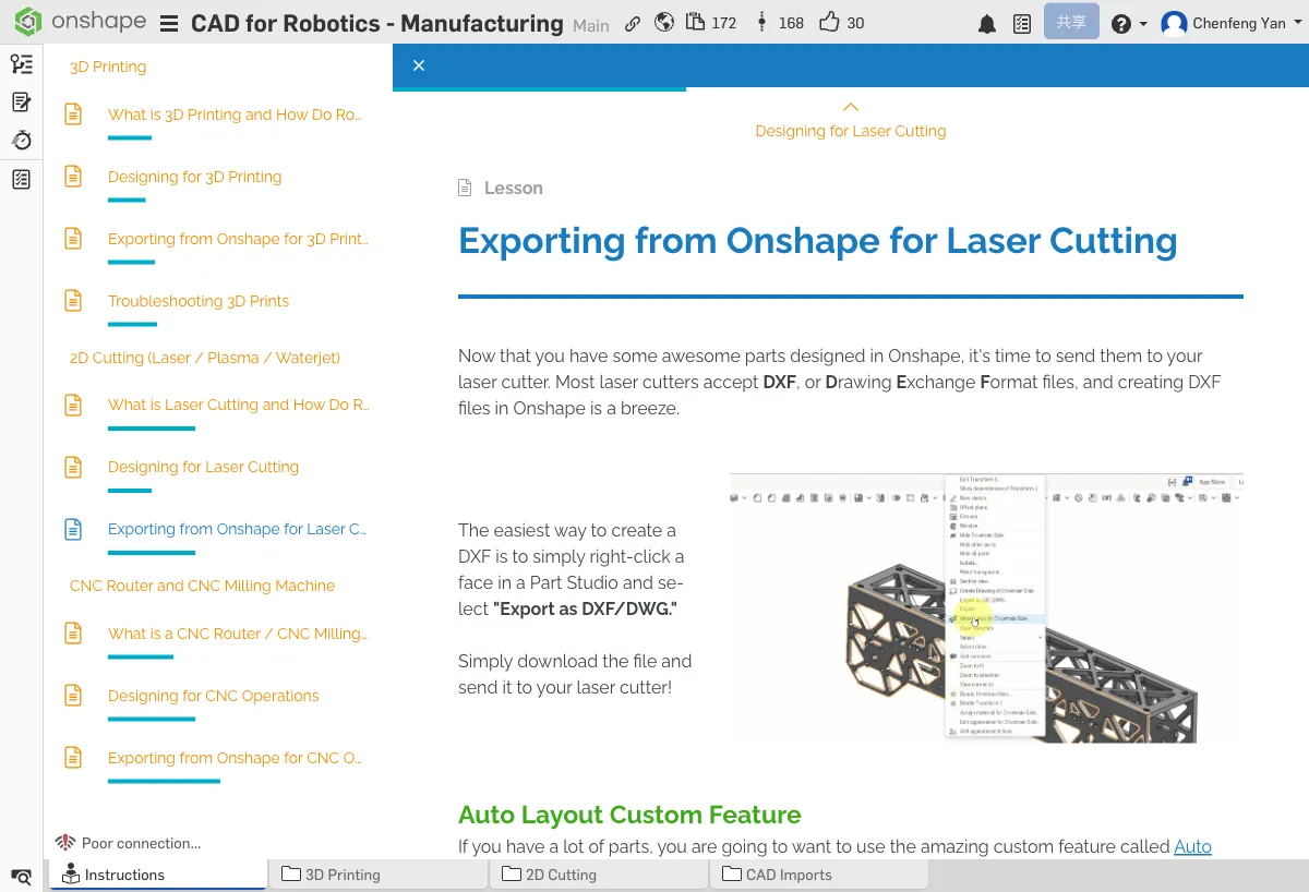
Exporting DXF
Auto Layout Custom Feature
Auto Layout is a very useful community custom feature that automatically arranges multiple parts on a sheet of material to maximize material utilization.
Single Sheet Export
- Select the face of the part to export
- Right-click → Export as DXF
- Verify the exported lines are complete
Multi-Sheet Export
If there are too many parts for one sheet, you'll need to group and arrange them, then export sheet by sheet.

Color Coding
Many laser cutting services require different colors to distinguish operations:
- Red — Cut lines (cutting through the material)
- Blue — Score lines (surface engraving only)
- Black — Raster engraving (filled areas)
Export Formats
- DXF — The most commonly used format for laser cutting
- SVG — Some cutting services also accept this format
Try selecting a flat face of a part in Onshape and right-click to export as DXF. If you have access to a laser cutter, try cutting it out.
Quick Quiz
What is the width of the cut made by the laser beam called?
What You Learned in This Chapter
- Laser cutting creates parts from 2D sheet material
- Kerf needs to be accounted for in your design
- Use DXF format to export cutting files