Building a Drivetrain Pod
Open your copied document in Onshape and switch to the Drivetrain Pod tab
A. Insert and Fasten a C-Channel
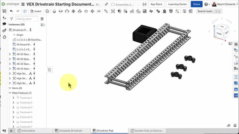
An assembly starts empty. You need to "Insert" parts from the parts library — think of it like taking screws and plates out of a toolbox and placing them on the table. After inserting, parts float in space, and you use "Mates" to lock them into the correct position.
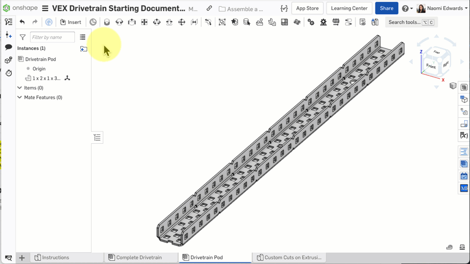
Step 1: Switch Tabs
Find the Drivetrain Pod tab at the bottom of the document and click to switch to it.
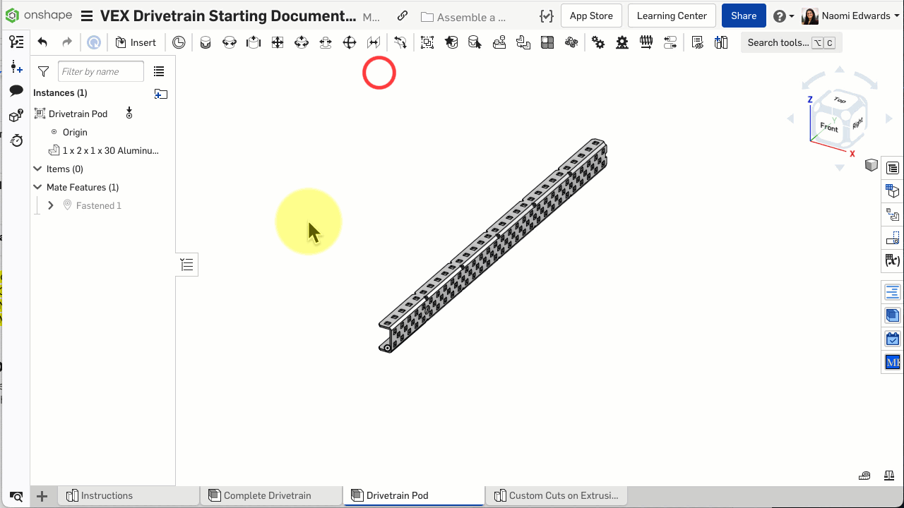
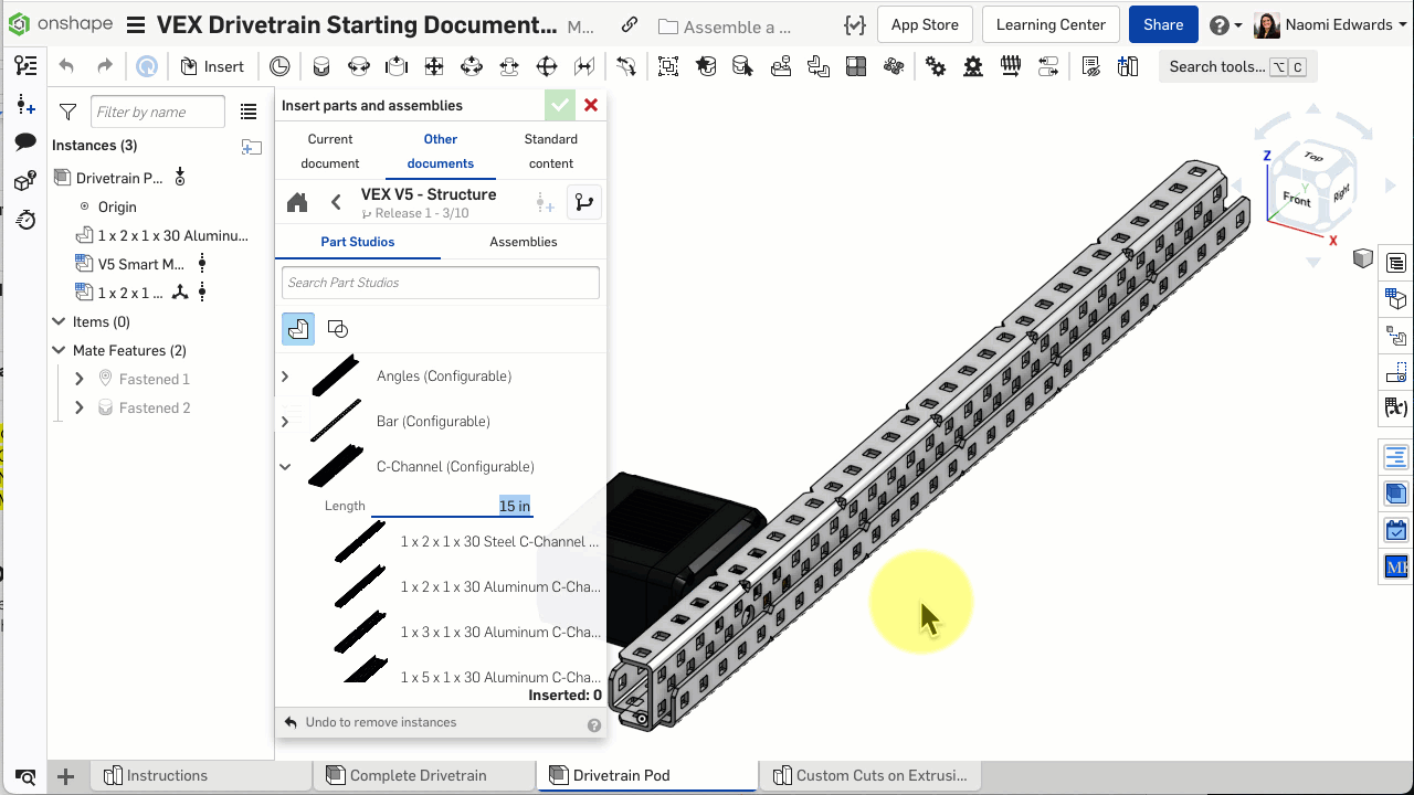
Step 2: Insert the C-Channel

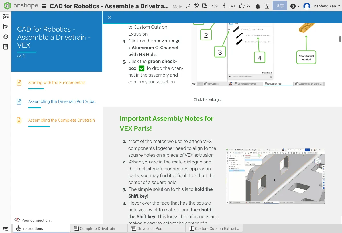
- Click the Insert button in the toolbar
- Select Current document
- Find Custom Cuts on Extrusion
- Select 1x2x1x30 Aluminum C-Channel with HS Hole
- Click the green checkmark to confirm
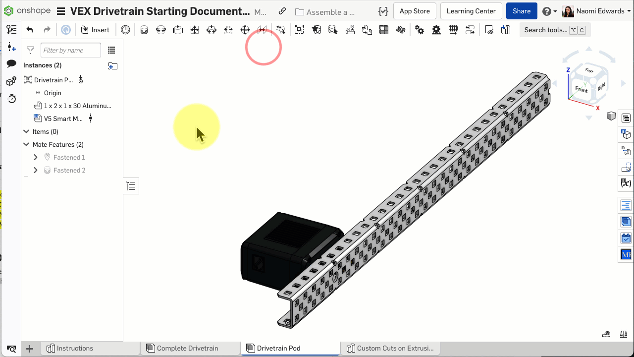
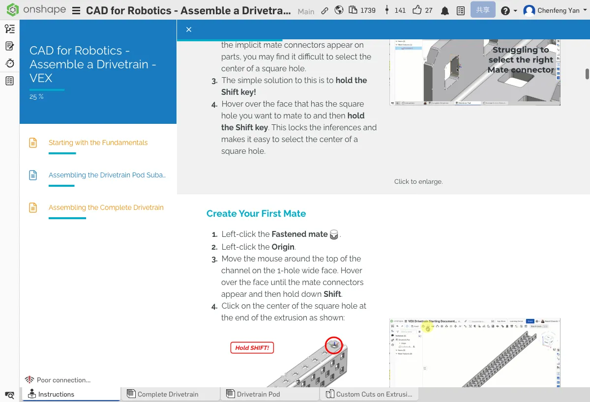
Most mates require aligning to the center of a square hole. Hold the Shift key to lock inferred points, making it easy to precisely select the center of a square hole.
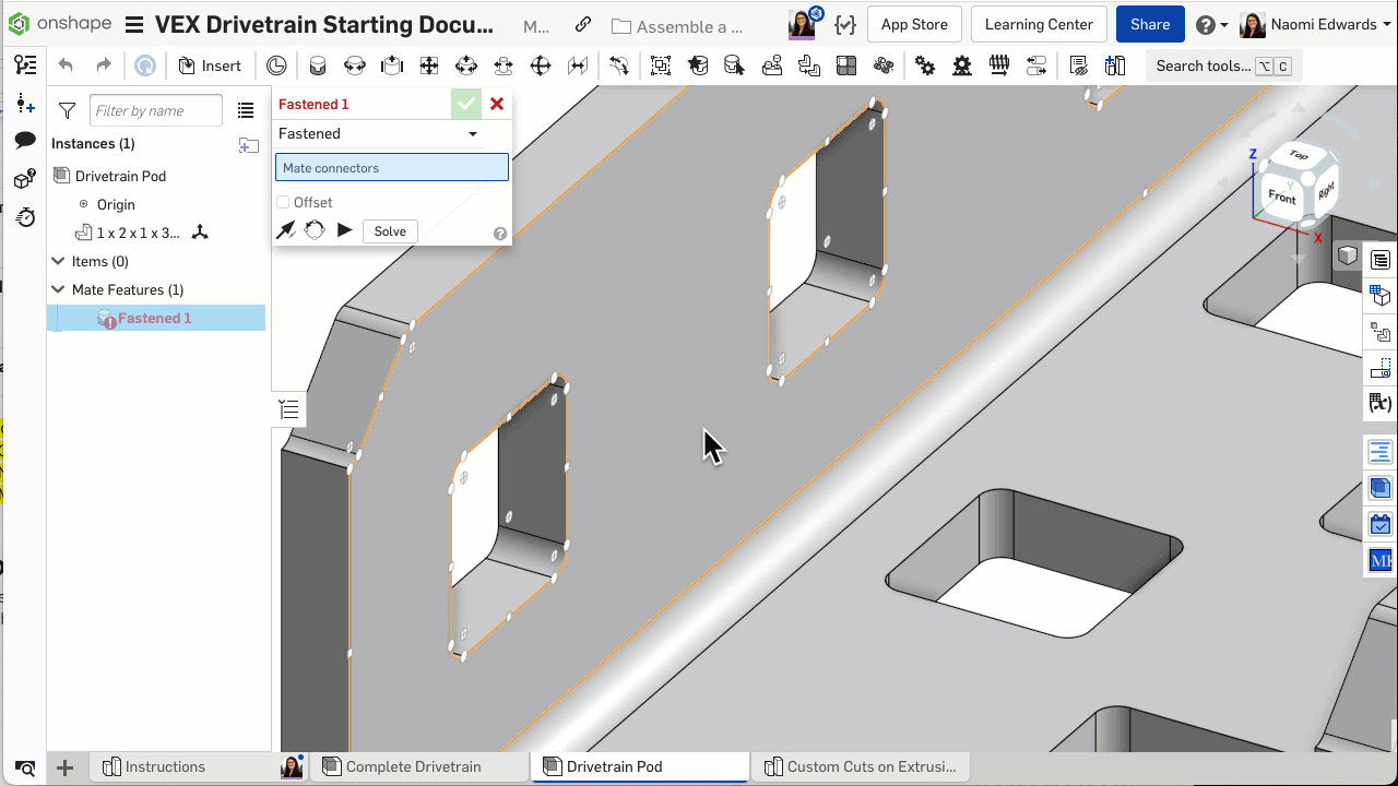
Step 3: Create the First Fastened Mate
- Click the Mate tool
- For the first connector, select the assembly's Origin
- For the second connector, select the center of a square hole on the C-Channel
- If the orientation is wrong, click Reorient secondary axis to adjust
- Click the green checkmark to confirm
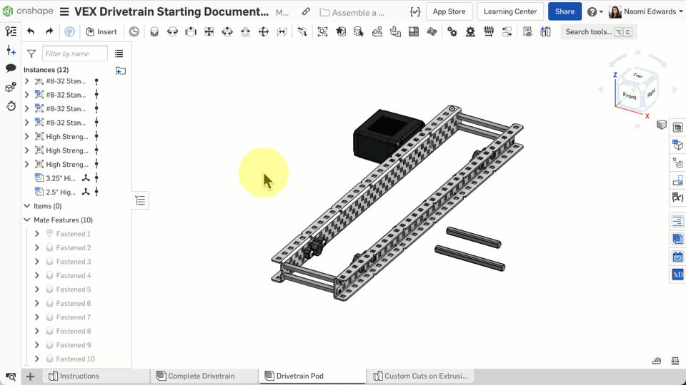
The C-Channel should be firmly fixed at the assembly origin, not floating.
No worries, many people run into issues with this step!
If the C-Channel didn't appear in the assembly: 1) Make sure you clicked the green checkmark to confirm insertion 2) Press F to see if the part flew out of view 3) Check whether the part name appears in the instance list on the left
Common Issues
- C-Channel orientation is wrong? — In the Mate dialog, click Flip primary axis or Reorient secondary axis to adjust
- Can't select the square hole center? — Remember to hold Shift to lock the inferred point, then slowly move to the center of the square hole
B. Install the Motor and Second C-Channel
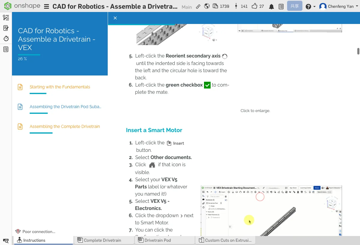
Step 4: Insert the Smart Motor
- Click Insert → Other documents
- Find your VEX V5 Parts label
- Open VEX V5 - Electronics
- Select Smart Motor (18:1)
- Click the green checkmark to confirm
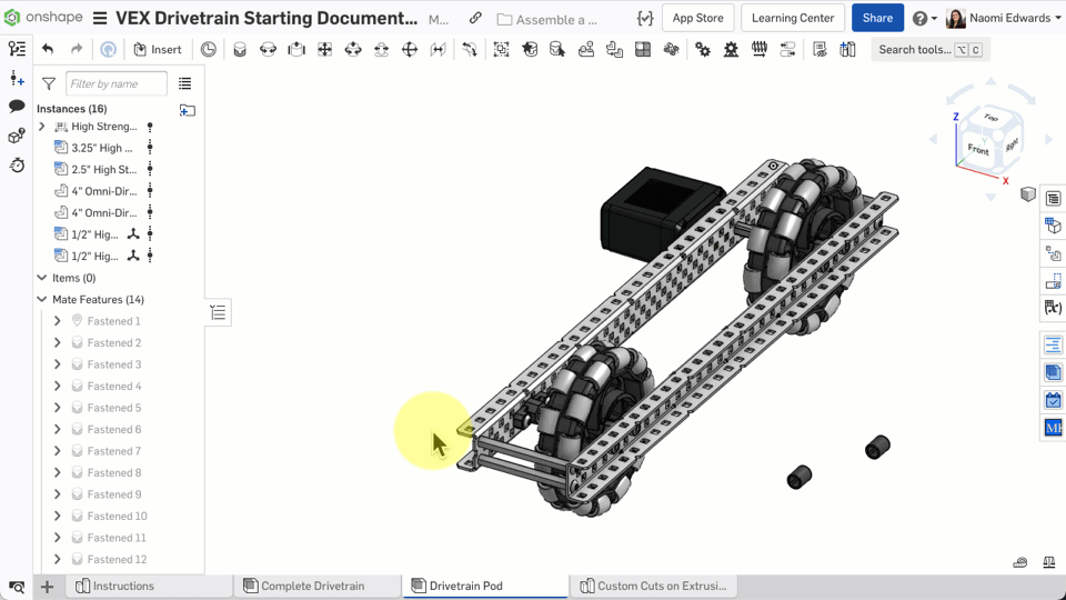
Step 5: Fasten the Motor to the C-Channel
- Create a Fastened mate
- First connector: the motor's threaded mounting boss
- Second connector: a square hole on the C-Channel (aligned with the large round hole)
- Use Reorient or Flip to adjust the motor orientation
- Confirm the motor sits flush against the C-Channel
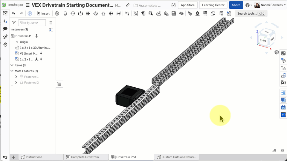
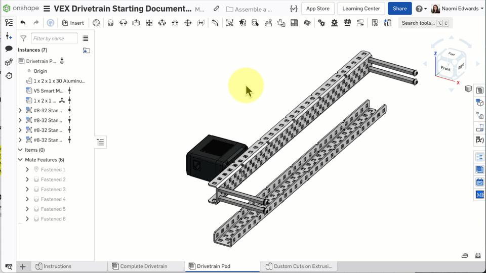
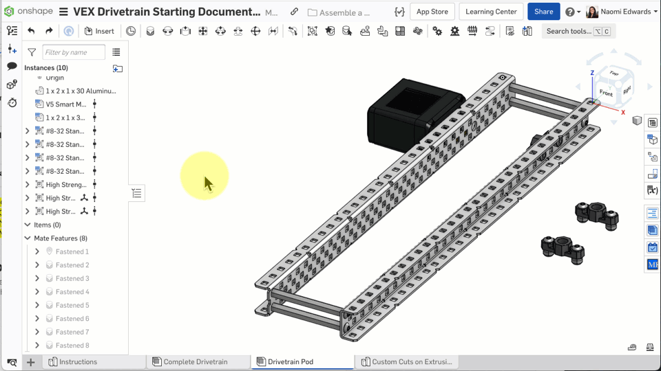
Step 6: Insert the Second C-Channel
- Click Insert → Other documents → VEX V5 Parts
- Open VEX V5 - Structure
- Select C-Channel Configurable
- Configure as 15 inches (30 holes), model 1x2x1x30 Aluminum
- Insert and fasten to the correct position with a Fastened mate
You should see a motor mounted on the first C-Channel and the second C-Channel in place.
No worries, many people run into issues with this step!
If the motor orientation is wrong: 1) Click the Reorient secondary axis button a few more times 2) Try Flip primary axis 3) There are only 4 possible orientation combinations — try each one until it's right
Common Issues
- Can't find the parts library? — Make sure you added the "VEX V5 Parts" label in Chapter 4
- Motor position is wrong? — Refer to the completed model in the Complete Drivetrain tab to compare motor placement
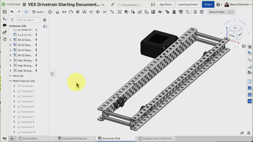
C. Install Standoffs and Bearings
Step 7: Insert Standoffs
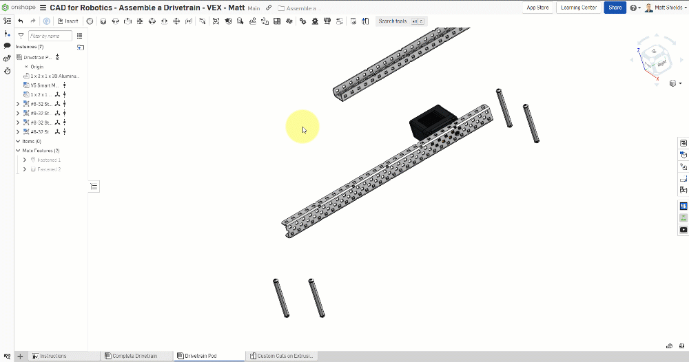
- Click Insert → Other documents → VEX V5 Parts
- Open VEX V5 - Spacers and Standoffs → Assemblies
- Select #8-32 Standoff with Screw(s)
- Configure the length to 2.5 inches
- Insert 4 of them
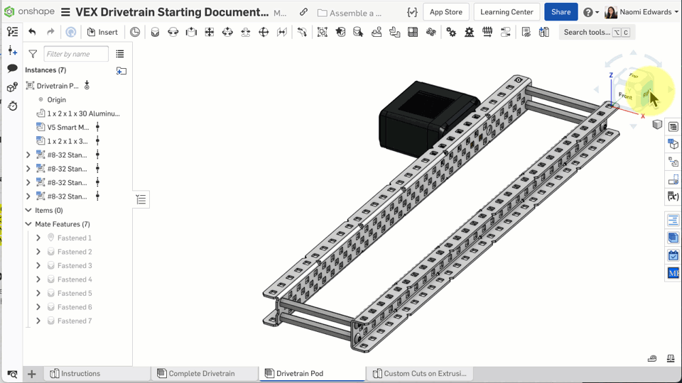
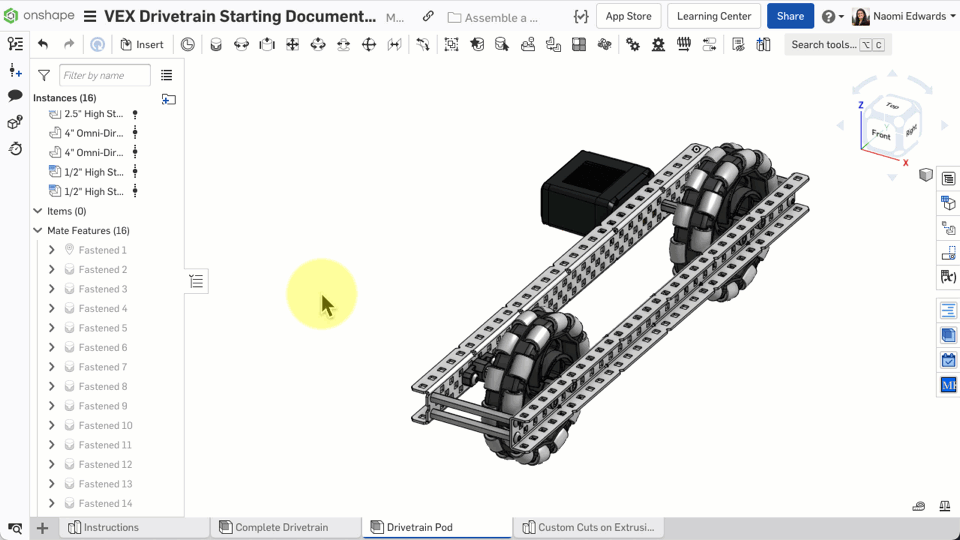
Step 8: Fasten Standoffs to the C-Channel Corners
- Create a Fastened mate for each standoff
- Connect the bottom of each standoff to the four corner square holes on the first C-Channel
Step 9: Fasten the Second C-Channel to the Standoff Tops
- Create a Fastened mate
- Align the second C-Channel to the tops of the 4 standoffs
- The two C-Channels should now be connected in parallel by the standoffs
Step 10: Insert Bearings
- Click Insert → VEX V5 - Bearing, Collars, and Inserts → Assemblies
- Select High Strength Shaft Bearing with Screws
- Insert 3 bearings
- Use Fastened mates to fix the bearings to the designated positions on the C-Channel
Step 10b: Fasten Each Bearing
- Create a Fastened mate for the first bearing, aligned to the round hole on the C-Channel
- Repeat for the second and third bearings at their corresponding positions
- Confirm all 3 bearings are in the correct holes
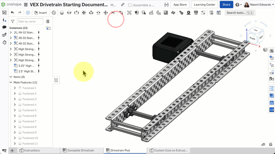
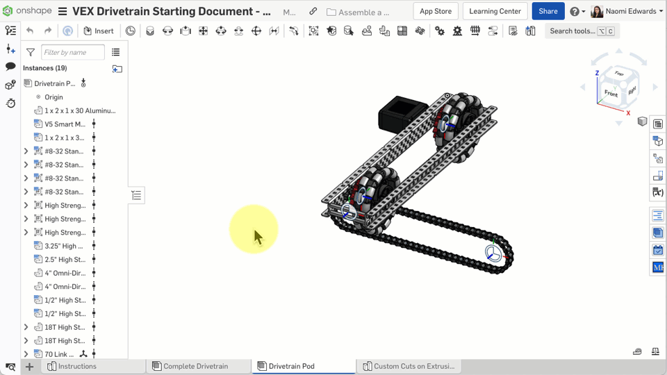
Check: Two C-Channels + 4 standoffs + 3 bearings, all correctly installed.
Common Issues
- Wrong standoff length? — After inserting, you can modify the Configuration in the left panel. Confirm it's set to 2.5 inches
- Second C-Channel won't align? — Fasten one corner first, then fasten the remaining corners one by one
- Not sure about bearing positions? — Refer to the completed model in the Complete Drivetrain tab
D. Install Shafts, Wheels, and Chain
Step 11: Insert Shafts
- Click Insert → VEX V5 - Shafts
- Select High Strength Shaft
- Insert two: one 3.25 inch and one 2.5 inch
- Use Fastened mates to fix the shafts to the bearing centers
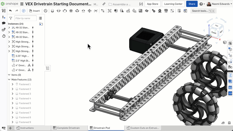
Step 12: Install Wheels
- Click Insert → VEX V5 - Wheels & Rollers
- Select 4" Omni Wheel
- Insert 2
- Use Fastened mates to fix the wheels to the shafts on the outside of the bearings
Step 13: Install Spacers
- Click Insert → VEX V5 - Spacers and Standoffs
- Select High Strength Shaft Spacer, configure as 1/2 inch
- Insert 2
- Use Fastened mates to fix the spacers to the shafts next to the wheels
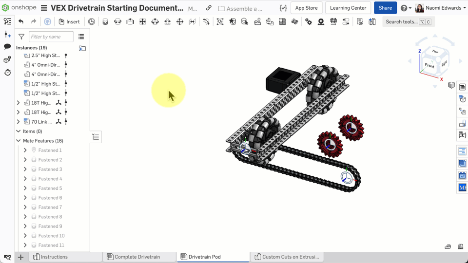
Step 14: Install Sprockets and Chain
- Click Insert → VEX V5 - Sprockets and Chain
- Insert 18T HS Sprocket (18-tooth high strength sprocket) x 2
- Insert 70 Link Chain, configured for 18T, 18T, 10 inch C2C
- Use Fastened mates to fix the sprockets next to the spacers
- Use a Fastened mate to fix the chain to the sprockets
Step 15: Final Details
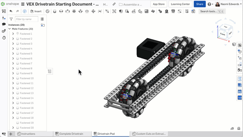
- Copy and paste a spacer: Select an existing spacer → Copy → Paste, then change the configuration to 1/8 inch
- Use a Fastened mate to fix it in the correct position
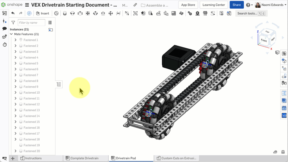
- Insert 2 screws to secure the motor
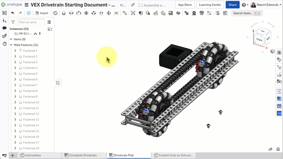
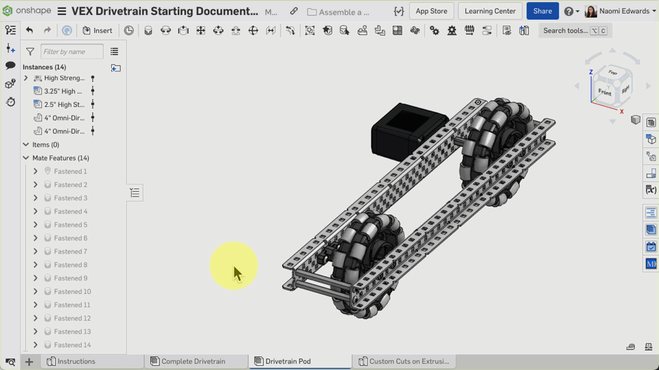
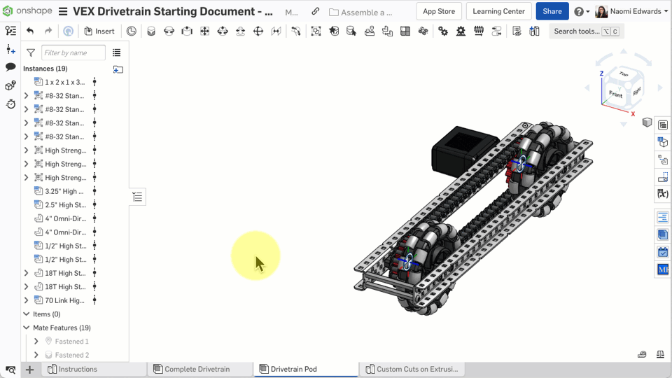
Your Drivetrain Pod should contain: C-Channel x 2, motor x 1, standoffs x 4, bearings x 3, shafts x 2, wheels x 2, spacers, sprockets x 2, chain x 1. Compare with the reference model in the Complete Drivetrain tab!
Common Issues
- Chain shape looks wrong? — Make sure the C2C (Center to Center) distance in the chain configuration is correct — it should be 10 inches
- Wheels won't spin? — This is normal because we're using Fastened mates (fixed). If you wanted the wheels to spin, you'd use a Revolute mate, but for this tutorial, fixed is fine
- Too many parts to remember positions? — Refer to the completed model in the Complete Drivetrain tab at any time
What You Learned in This Chapter
- Fastened mate locks parts to a specific position
- Hold Shift to select the mate connector at the center of a square hole
- Find and insert parts from the VEX V5 Parts label
Quick Quiz
What type of Mate completely locks a part in place?