In-Context Sketching
The Problem
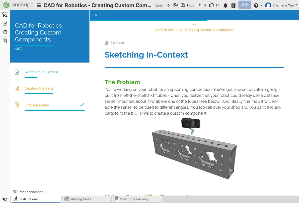
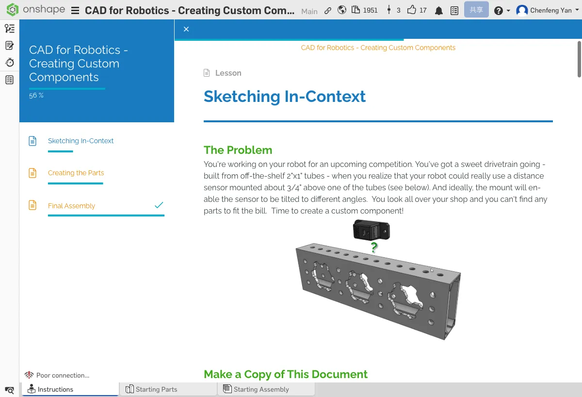
You're building a competition robot with a 2"x1" tube chassis. You need to mount a distance sensor 3/4" above the tube and make the angle adjustable. You've searched the workshop but can't find a suitable part -- it's time to design your own!
Imagine making a phone case -- you'd measure the phone directly, not draw from memory. "In-context modeling" means the same thing: designing new parts inside the assembly environment, where you can reference edges and faces of existing parts to ensure a perfect fit.
Copy the Document
As before, start by copying the tutorial document to your own Onshape account.
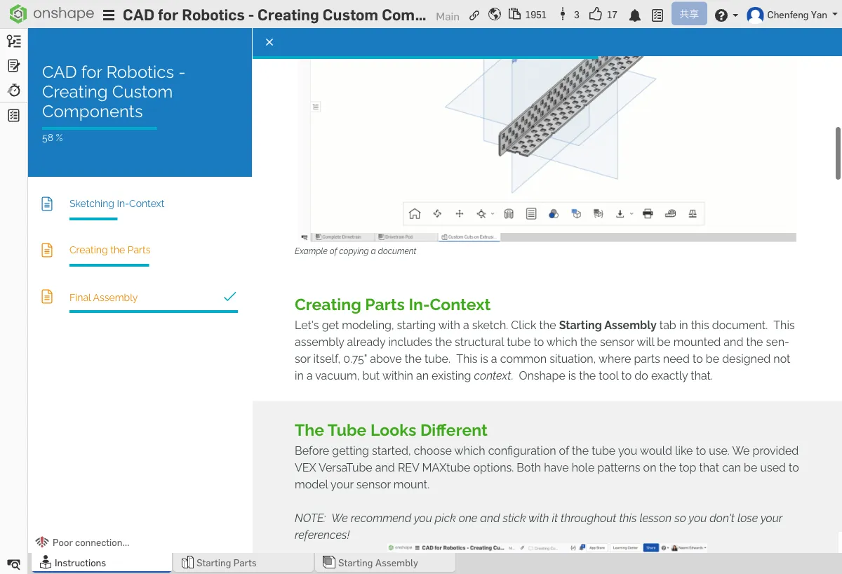
Click to open the Onshape tutorial document in a new tab, then copy it to your account
What is In-Context Modeling?
Normal modeling starts from scratch in an empty environment. In-Context modeling means designing parts inside the assembly environment. You can directly reference the geometry (edges, faces, holes) of existing parts, ensuring your new part fits precisely with the old ones.
Open the Starting Assembly tab -- the tube and distance sensor are already placed inside.
Choose a Tube Type
The document provides two tube options: VEX VersaTube and REV MAXtube. Pick either one -- the steps are exactly the same.
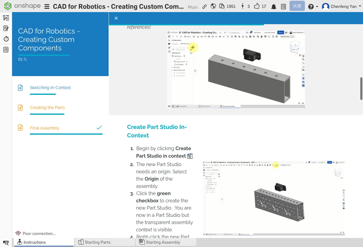
Create a Part Studio In-Context
- In the assembly, click Create Part Studio in context
- The system will ask you to choose an origin -- select Origin
- Click the green checkmark ✓ to confirm
- You'll enter a new Part Studio with the assembly shown transparently in the background
- In the feature tree on the left, right-click the new Part Studio and rename it to Sensor Mount
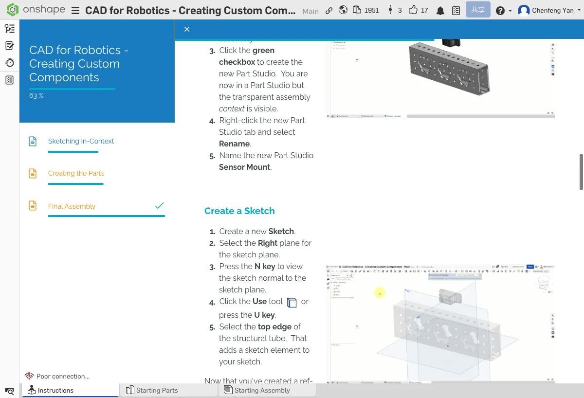
Create a Sketch
- Click the Sketch tool → select the Right plane
- Press N to switch to the front view
- Use the Use tool (shortcut U) → select the top edge of the tube
The Use tool projects the tube's top edge onto your sketch plane. This line is a reference between you and the assembly -- if the tube moves, your part will update accordingly.
After entering the Part Studio, you should see the semi-transparent tube and sensor in the background. The top edge referenced with the Use tool should appear as a purple line.
No worries, many people run into issues here!
If you can't see the transparent assembly: 1) Check if the Assembly context dropdown is set to Context 1. 2) If the dropdown is empty, the Part Studio wasn't created with the correct Origin selected. 3) Try deleting this Part Studio tab and recreating it using Create Part Studio in context.
Draw Lines and Arcs
- Select the Line tool (shortcut L)
- From the left endpoint of the Use line, draw a vertical line upward
- Draw a horizontal line to the right
- Draw another vertical line downward
- Switch to the Tangent arc tool and draw an arc to connect
- Use the Line tool again to draw two more lines to close the profile
⚠️ If the model disappears
- Lost sight of the model while drawing? — Press F to return to the full view (Zoom to fit)
Add Dimensions and Constraints
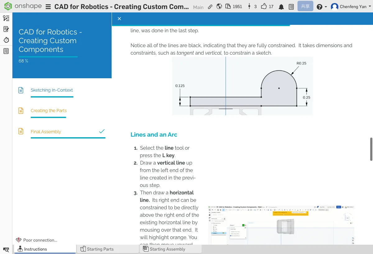
- Select the Dimension tool (shortcut D)
- Dimension the left vertical line: 0.125 in
- Dimension the right vertical line: 0.25 in
- Dimension the arc radius: 0.25 in
- Add a Tangent constraint (shortcut T) -- to make the arc smoothly transition into the straight lines
- Add a Vertical constraint (shortcut V) -- to keep vertical lines truly vertical
Blue = Under-constrained (can still move freely)
Black = Fully constrained (position and size are completely determined)
Before committing the sketch, make sure all lines have turned black!
All lines should be black. If any are still blue, you need to add more dimensions or constraints.
No worries, many people run into issues here!
If sketch lines aren't turning black: 1) Blue = some lines aren't constrained yet, try adding more dimensions. 2) Use the Dimension tool (D key) to dimension each line. 3) Check if any lines are disconnected -- zoom in to verify that endpoints actually coincide.
⚠️ Common Issues
- Still have blue lines after adding dimensions? — Check if you're missing tangent or vertical constraints. These geometric constraints are also key to "locking" line positions.
- Entered the wrong dimension? — Double-click the dimension number to edit it.
Complete the Sketch
Once all lines have turned black, click the green checkmark ✓ to commit the sketch.
The sketch has been committed and you can see Sketch 1 in the feature tree. In the next chapter, we'll extrude this sketch into a solid part.
From the teaching guide: How do you know you're in In-Context mode? What changes in the workspace when you toggle the context on and off?
Quick Quiz
In an Onshape sketch, what do blue lines mean? What about black lines?
What You Learned in This Chapter
- In-context modeling lets you reference geometry from the assembly
- The Use tool projects existing edges onto your sketch
- Blue lines = under-constrained, black lines = fully constrained